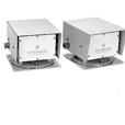
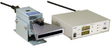
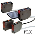
BWF-17/27(CC-Link compatible)
|
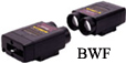
BWF-17/27 |
OPTICAL DATA TRANSMISSION DEVICE |
 |
Direct connection to CC-Link |
Feature
- This device is a serial type optical data transmission device which is able to connect to CC-Link directly.
- Max. 112 points and 15 words can be transmitted and max. 42 pcs can be connected to 1 master unit.
Specifications
|
Model No. |
BWF-17A/17B |
BWF-27A/27B |
||||||||||||
|
Power source/current consumption |
24VDC(18 to 30VDC), 100mA or less(when 24VDC) |
|||||||||||||
|
Optical communication |
Transmission distance |
100m |
200m |
|||||||||||
|
Directional angle |
±2° |
±1° |
||||||||||||
|
Transmission method |
Full-duplex two-way transmission |
|||||||||||||
|
Transmission speed |
19,200bps |
|||||||||||||
|
Modulation method |
FSK modulation |
|||||||||||||
|
Modulated frequency |
A type(Transmission : 5.5MHz, reception : 6.0MHz) |
|||||||||||||
|
CC-Link part |
Communication speed |
10Mbps/5Mbps/2.5Mbps/625kbps/156kbps(Changeover by switch) |
||||||||||||
|
Communication system |
Polling system |
|||||||||||||
|
Synchronous system |
Frame synchronous system |
|||||||||||||
|
Transmission path |
RS-485bus |
|||||||||||||
|
Transmission format |
HDLC conformity |
|||||||||||||
|
Remote station Nos. |
1 to 64 |
|||||||||||||
|
Connecting cable |
CC-Link exclusive cable |
|||||||||||||
|
Max. extending cable |
|
|||||||||||||
|
Terminator* |
110Ω(Connected between DA and DB of both ends unit) |
|||||||||||||
|
Connecting system |
Connector type(terminal for DC power and FG) |
|||||||||||||
|
Ambient illuminance |
20,000 lx(Halogen and mercury lamp) |
|||||||||||||
*In case of using the cable with impedance, 130Ω, make sure to be off for terminator switch on BWF and connect terminator with 13 0Ω between DA and DB.
External dimension

Connection

|
Connector for CC-Link unit |
|
|
1 |
FG |
|
2 |
SLD |
|
3 |
DG |
|
4 |
DB |
|
5 |
DA |
Note) Don't make a wiring with main circuit, high voltage cable or load cable because of noise or surge induction.
More Info PriceDMC(DeviceNet compatible)

|
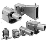
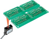
DMC-GB1/HB1 |
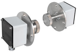
OPTICAL DATA TRANSMISSION DEVICE |
 |
Direct connection to DeviceNet PLC |
Feature
- This device is 8bit optical data transmission device which is able to connect to PLC for DeviceNet.
- This is able to optical communication with parallel type DMS-G/HB and DM-G/HB.
- Max. 63 pcs can be connected to 1 master unit.
Specifications
|
Model No. |
DMC-GB1 |
DMC-HB1 |
||||||||||||||||
|
Direction |
HEAD-ON |
SIDE-ON |
||||||||||||||||
|
Power source |
24VDC(+15%, -10%, ripple 0.5Vp-p or less), PLC side : 40mA or less, Device side : 50mA or less |
|||||||||||||||||
|
Transmission capacity |
Input 8 bits/output 8 bits(SELECT and GO can be transmitted by dip switch) |
|||||||||||||||||
|
Address setting |
Individual setting by dip switch |
|||||||||||||||||
|
Connection |
Connector : 5-pin(for PLC), 2-pin(for power source) |
|||||||||||||||||
|
Optical communication part |
Transmission distance |
0.6m* |
||||||||||||||||
|
Directional angle |
Full angle 30° |
|||||||||||||||||
|
Transmission method |
Half-duplex two-way transmission |
|||||||||||||||||
|
Transmission time |
40ms |
|||||||||||||||||
|
Modulation method |
Pulse modulation |
|||||||||||||||||
|
Detection method |
Parity check |
|||||||||||||||||
|
DeviceNet part |
Connecting system |
Multi-drop system |
||||||||||||||||
|
Communication speed |
500Kbps/250Kbps/125Kbps(Changeover by switch) |
|||||||||||||||||
|
Communication cycle time |
12.2msec(Connection Nos. 32 pcs at communication speed, 500kbit/s) |
|||||||||||||||||
|
Communication media |
Communication media |
|||||||||||||||||
|
Communication distance |
|
|||||||||||||||||
|
Max. Nos. of connection node |
64 pcs(including master unit, max. connectable slave 63 pcs) |
|||||||||||||||||
|
Ambient illuminance |
4,000 lx(Halogen and mercury lamp) |
|||||||||||||||||
|
Protective structure |
IP40(IEC standard) |
|||||||||||||||||
*3m type is also available.
External dimension

Connection

5P side(PLC connection)
|
Colors |
Signals |
Functions |
Position |
|
Red |
+24V |
Power |
1 |
|
White |
Can+ |
Signal |
2 |
|
Shield |
Shield |
3 |
|
|
Blue |
Can- |
Signal |
4 |
|
Black |
+0V |
Power |
5 |
2P side(Power source)
|
Colors |
Signals |
Functions |
Position |
|
+24V |
Power |
1 |
|
|
+0V |
Power |
2 |
Note) Don't make a wiring with main circuit, high-voltage line or load wire because it is not affected by noise and surge induction.
More Info PriceDMM(CC-Link compatible)
|
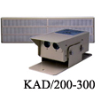
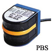
DMM-GB/HB |
OPTICAL DATA TRANSMISSION DEVICE |
|
|
This device is able to connect directly to CC-Link system. |

Specifications
|
Model No. |
DMM-GB1 |
DMM-HB1 |
DMM-GC1 |
DMM-HC1 |
||||||||||||||||||
|
Direction |
HEAD-ON |
SIDE-ON |
HEAD-ON |
SIDE-ON |
||||||||||||||||||
|
Power source |
24VDC(18 to 30VDC available) |
|||||||||||||||||||||
|
Optical communication part |
Transmission distance |
0 to 1m*1 |
0 to 3m*2 |
|||||||||||||||||||
|
Directional angle |
Full angle 30° |
Full angle 26° |
||||||||||||||||||||
|
Transmission capacity(I/O) |
8BIT/8BIT |
16BIT/16BIT*3 |
||||||||||||||||||||
|
Transmission method |
Half-duplex two-way transmission |
|||||||||||||||||||||
|
Transmission time |
40ms |
|||||||||||||||||||||
|
Modulation method |
Pulse modulation |
FSK modulation |
||||||||||||||||||||
|
Detection method |
Parity check |
|||||||||||||||||||||
|
CC-Link part |
Transmission speed |
10Mbps/5Mbps/2.5Mbps/625kbps/156kbps(Changeover by switch) |
||||||||||||||||||||
|
Communication system |
Polling system |
|||||||||||||||||||||
|
Synchronous system |
Frame synchronous system |
|||||||||||||||||||||
|
Transmission path |
RS-485bus |
|||||||||||||||||||||
|
Remote station Nos. |
1 to 64 |
|||||||||||||||||||||
|
Occupied station |
1 station |
|||||||||||||||||||||
|
Connecting cable |
CC-Link exclusive cable and CC-Link high quality cable |
|||||||||||||||||||||
|
Max. extending cable*4 |
|
|||||||||||||||||||||
|
Connecting system |
Connector type(5 pins) |
|||||||||||||||||||||
|
Ambient temperature/ humidity |
-10 to +50 degrees C, 85%RH or less(Not condensing) |
|||||||||||||||||||||
|
Ambient illuminance |
Halogen 4,000 lx or less, mercury lamp 4,000 lx or less |
|||||||||||||||||||||
*1. 3m type is also available.
*2. Distance can be changed by adjuster.
*3. 16th bit can be changed to Select input/GO output by input changeover switch.
*4. Total extended distance changes depending on total
External dimension
External dimension

Connection

5P side(CC-Link connection)
|
Signals |
Functions |
Position |
|
DA |
Signal cable |
1 |
|
DAR |
Terminator provided |
2 |
|
DB |
Signal cable |
3 |
|
DG |
Signal GND cable |
4 |
|
SLD |
Shield cable |
5 |
Note) If this device is connected to terminator, it is shorted between DA and DAR by the wire with 1mm.
3P side(Power source)
|
Signals |
Functions |
Position |
|
FG |
Ground |
1 |
|
+24V |
DC power |
2 |
|
+0V |
DC power |
3 |
Note) Don't make a wiring with main circuit, high-voltage line or load wire because it is not affected by noise and surge induction.
More Info PriceHOKUYO MARKASINA A?T ?R?N GRUPLARI