Greatest reference in our business is our successful past

GF4C Rotary limit switch

GF4C Rotary limit switch

GF4C Rotary limit switch

SPECIFICATIONS
  • The limit switch can be customised.
  • Switches available: 1NC and 1NC+1NO, with positive mechanical contact opening, snap or slow action.
  • Available with front fixing flange.
  • Available with the same or different revolution ration on the two motion entries.
  • Further information available on the technical documentation PRCA0EAN00.
TECHNICAL CHARACTERISTICS
  • Operational temperature -25°C / +70°C
  • Degree of protection IP 65
  • Insulation category Class II
  • Rated operational current 3 A
  • Rated operational voltage 250 Vac
  • Mechanical life 1x10⁶ operations
  • Markings and homologations CE (UL, cUL on request)

Overall dimensions


Cross section


DESCRIPTION

The rotary limit switch is used to control the movement of industrial machinery. It operates as an auxiliary controller of electrical motors through a power interface, such as a contactor or PLC. Suitable for heavy duty, its shaft is connected to the motor and, after a set number of revolutions, the cams operate the switches, thus starting the predetermined movement. A worm gear and a helical toothed gear combined with one or more pairs of straight toothed gears are used for the transmission of the movement from the input shaft to the output shaft.

Revolution ratios, ranging from 1:1 to 1:969, result from the use of different combinations of gear wheels between the input shaft and the output shaft, which is connected to the cams operating the switches.
Transmission and gear driving shafts are made of stainless steel to prevent oxidation and wear. The gear wheels and the driving bushes are made of self-lubricating thermoplastic material, suitably chosen to reduce the wear to a minimum and to maintain the accuracy of the couplings over time. Sintered bronze bushes are moulded into the base of the limit switch to optimise the shaft rotation and to prevent rubbing with plastic material.

Each cam can be set with great accuracy thanks to the cam adjusting screws. The auxiliary switches are of a positive opening type, thus suitable for safety functions. It is available with direct control switches for operating directly on the motor.
The cam-switch sets can be substituted for potentiometers suitable for the connection to electronic equipment. Each output of the limit switch can be set with a different revolution ratio to allow for a diversified control of the machinery to meet special requirements.

Materials and components are wear resistant and protect the equipment against water and dust. The limit switch is available with a flange for direct coupling to the motor and it can be customised with labels and colours according to the customer’s requirements.

GF4C: SHORTCUTS
Sales Documents
Technical Documents
Use and maintenance instructions
Catalogues in other languages
Write to us
More Info Price

MF2C Rotary limit switch

MF2C Rotary limit switch

MF2C Rotary limit switch

SPECIFICATIONS
 
The limit switch can be customised.

Switches available: 1NC and 1NC+1NO, with positive mechanical contact opening, snap action.

Available with potentiometer/encoder.

Further information available on the technical documentation PRCA0EAL00.
 
TECHNICAL CHARACTERISTICS
 
Operational temperature -25°C / +70°C

Degree of protection IP 65

Insulation category Class II

Rated operational current 3 A

Rated operational voltage 250 Vac

Mechanical life 1x10⁶ operations

Markings and homologations CE (UL, cUL on request)

Overall dimensions


Cross section


DESCRIPTION

The rotary limit switch is used to control the movement of industrial machinery. It operates as an auxiliary controller of electrical motors through a power interface, such as a contactor or PLC. Suitable for heavy duty, its shaft is connected to the motor and, after a set number of revolutions, the cams operate the switches, thus starting the predetermined movement.

A worm gear and a helical toothed gear combined with one or more pairs of straight toothed gears are used for the transmission of the movement from the input shaft to the output shaft. Revolution ratios ranging from 1:1 to 1:150 result from the use of different combinations of gear wheels between the input shaft and the output shaft, which is connected to the cams operating the switches.

Overall dimensions are suitable for assembly in small spaces. Transmission and gear driving shafts are made of stainless steel to prevent oxidation and wear. The gear wheels and the driving bushes are made of self-lubricating thermoplastic material, suitably chosen to reduce the wear to a minimum and to maintain the accuracy of the couplings over time. Sintered bronze bushes are moulded into the base of the limit switch to optimise the shaft rotation and to prevent rubbing with plastic material.

Each cam can be set with great accuracy thanks to the cam adjusting screws. The auxiliary switches are of the positive opening type, thus suitable for safety functions.The limit switch is available with direct control switches for operating directly on the motor.

Materials and components are wear resistant and protect the equipment against water and dust. The limit switch can be customised with labels and colours according to the customer’s requirements

 MF2C: SHORTCUTS
Sales Documents
Technical Documents
Use and maintenance instructions
Variant Form
Catalogues in other languages
Write to us
More Info Price

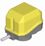
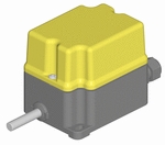
PF2C Rotary limit switch

PF2C Rotary limit switch

PF2C Rotary limit switch


SPECIFICATIONS
 
The limit switch can be customised.

Switches available: 1NC and 1NC+1NO, with positive mechanical contact opening, snap or slow action.

Available with potentiometer.

Available with front fixing flange.

Further information available on the technical documentation PRCA0EAM00.
 
TECHNICAL CHARACTERISTICS
 
Operational temperature -25°C / +70°C

Degree of protection IP 65

Insulation category Class II

Rated operational current 3 A

Rated operational voltage 250 Vac

Mechanical life 1x10⁶ operations

Markings and homologations CE (UL, cUL on request)

Overall dimensions


Cross section


DESCRIPTION
 
The rotary limit switch is used to control the movement of industrial machinery. It operates as an auxiliary controller of electrical motors through a power interface, such as a contactor or PLC. Suitable for heavy duty, its shaft is connected to the motor and, after a set number of revolutions, the cams operate the switches, thus starting the predetermined movement. A worm gear and a helical toothed gear combined with one or more pairs of straight toothed gears are used for the transmission of the movement from the input shaft to the output shaft.

Revolution ratios ranging from 1:1 to 1:295 result from the use of different combinations of gear wheels between the input shaft and the output shaft, which is connected to the cams operating the switches.
Transmission and gear driving shafts are made of stainless steel to prevent oxidation and wear. The gear wheels and the driving bushes are made of self-lubricating thermoplastic material, suitably chosen to reduce the wear to a minimum and to maintain the accuracy of the couplings over time. Sintered bronze bushes are moulded into the base of the limit switch to optimise the shaft rotation and to prevent rubbing with plastic material.

Each cam can be set with great accuracy thanks to the cam adjusting screws. The auxiliary switches are of a positive opening type, thus suitable for safety functions. It is available with direct control switches for operating directly on the motor.
The cam-switch sets can be substituted for potentiometers suitable for the connection to electronic equipment.

Materials and components are wear resistant and protect the equipment against water and dust. The limit switch is available with a flange for direct coupling to the motor and it can be customised with labels and colours according to the customer’s requirements
PF2C: SHORTCUTS
Sales Documents
Technical Documents
Use and maintenance instructions
Catalogues in other languages
Write to us

More Info Price

SF12C Rotary limit switch

SF12C Rotary limit switch

SF12C Rotary limit switch

SPECIFICATIONS
  • The limit switch can be customised.
  • Switches available: 1NC and 1NC+1NO, with positive mechanical contact opening, snap or slow action.
  • Available with front fixing flange.
  • Available with cable clamp for cable entry from below.
  • Available with the same or different revolution ration on the two motion entries.
  • Further information available on the technical documentation PRCA0EAO00.
TECHNICAL CHARACTERISTICS
  • Operational temperature -25°C / +70°C
  • Degree of protection IP 65
  • Insulation category Class I
  • Rated operational current 3 A
  • Rated operational voltage 250 Vac
  • Mechanical life 1x10⁶ operations
  • Markings and homologations CE (UL, cUL on request)

Overall dimensions


Cross section


DESCRIPTION

The rotary limit switch is a device used for controlling the movement of industrial machines.
It is an auxiliary control and therefore commands the machine via a power interface, such as a contactor (or a PLC). Suitable for heavy use, it is connected by a shaft to a motor so that after a certain number of revolutions the cams operate the switches to start the pre-set movement. A worm gear and a helical toothed gear combined with one or more pairs of straight toothed gears are used to transmit movement from the input shaft to the output shaft.

Transmission ratios result from the use of different combinations of gear wheels between the input shaft and the output shaft, which is connected to the cams that operate the switches. The gear ratio ranges from 1:1 to (1:9400).

Transmission and gear drive shafts are in stainless steel to prevent oxidisation and wear. The gear wheels and driving bushes are in self-lubricating thermoplastic to reduce wear to a minimum and to maintain the accuracy of the couplings over time. Sintered bronze bushes are moulded into the base of the limit switch, to optimise shaft rotation and prevent it rubbing against plastic.

Each cam can be regulated with great accuracy using the cam adjusting screws. The auxiliary switches are positive-opening and can be used for safety purposes. There is also a direct-control version, which allows direct control of the motor.

All the materials and parts used are resistant to atmospheric agents and guarantee that the device is water- and dust-proof.

Available with cable entry clamp from below.

The base of the limit switch, in die-cast aluminium, has excellent resistance characteristics and ball bearings to optimise rotation of the shaft and prevent rubbing.

SF12C: SHORTCUTS
Sales Documents
Technical Documents
Use and maintenance instructions
Catalogues in other languages
Write to us
More Info Price

TER Tecno Elettrıca Ravası MARKASINA A?T ?R?N GRUPLARI

Anemometer
Anemometer
Control Systems
Control Systems
Display
Display
Foot switches
Foot switches
Joysticks
Joysticks
Pendant control stations
Position limit switches
Radio remote controls
Rotary limit switches
Safety Switch
Safety Switch
Sensors
Sensors
Slip ring collectors