Çalışmalarımızdaki en büyük referansımız, geride bıraktığımız başarı dolu
Model 1735

Flashing relays
Model 1735
2 Kontak
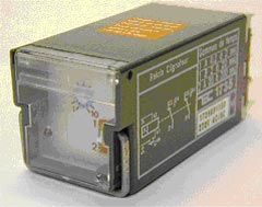 |
 1735 |
| DESCRIPTION |
|
|
Multirange flashing relay - 2 CO contacts - 5 A.
Pluggable on front wiring socket (9705) or rear wiring socket (9723) Detailed table of the coil resistance data is available in the technical support pages of this site or can be sent upon request. |
| Dimensions | Connection | ||
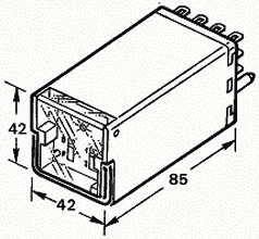 |
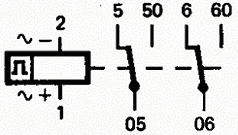 |
| OPERATION PRINCIPLE |
|
| Timing range selector on front face : 1-A : 0,2 to 2 s 1-B : 2 to 20 s 2-A : 20 to 200 s Timing adjustable by potentiometer. Visualisation of the output state by LED. |
| TECHNICAL FEATURES |
||
| Function | flashing | |
| Presentation | under cover | |
| Connection | on front or rear wiring socket | |
| Number of mechanical operations | > 30.000.000 | |
| Operating temperature | - 25 to + 55°C | |
| Storage temperature | - 40°C to + 80°C | |
| Climatic protection | reinforced climatic protection | |
| Shock voltage | 50 g - 11 ms | |
| Dielectric strength | 2,5 KV - 50 Hz | |
| Insulation resistance | > 1.000 MOhms (500 VDC) | |
| Weight | 130 g. | |
| COIL DATA |
||||
| Direct current | Alternative current | |||
| Min. nominal voltage DC | 12 V | 220 V | ||
| Min. nominal voltage AC | 127 V | 220 V | ||
| Operating range | -20/+10% of nominal voltage | |||
| Power requirement | max 4 VA | |||
| CONTACTS |
||
| Number of contacts | 2 | |
| Contacts material | silver alloy with gold flash | |
| Max. load current | 5 A per contact | |
| Low power switching | 100 VA with min. voltage 1 V or I Min 1 mA | |
| Short-circuit load | 100 A / 30 ms | |
| Response time | DC < 20 ms - AC < 20 ms | |
| Bounce time | 100 ms | |
| OPERATION DIAGRAM |
|
| FUNCTIONS | |
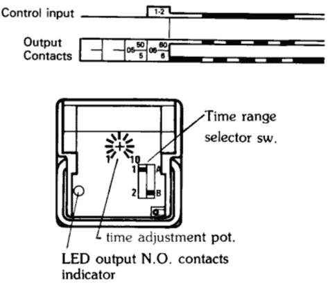 |
|
Detaylı Bilgi Fiyat
Model 2820

Flashing relays
Model 2820
2 Kontak
 |
 2820 |
| DESCRIPTION |
|
|
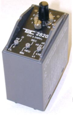
Universal timer relay - 2 contacts.
Pluggable on the following sockets : 9946, 9244, 9246. |
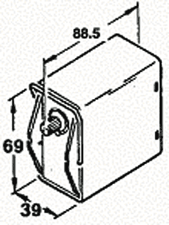
| Dimensions | Connection | ||
 |
 |
| OPERATION PRINCIPLE |
|
| Timing ranges : * sec : 0.01-0.1 / 0.1-1 / 1-10 / 10-100 * min : 0.01-0.1 / 0.1-1 / 1-10 / 10-100 * h : 0.01-0.1 / 0.1-1 / 1-10 / 10-100 Visualisation by red state LED and green voltage presence LED. See the operation diagram hereafter. !! any modification of the choice of the form or of the multiplier of a timing in use will be validated only after a power supply break !! |
| PLAN |
|
 |
|
| TECHNICAL FEATURES |
||
| Function | timer (F, O, CL, PF) | |
| Presentation | under cover | |
| Connection | pluggable on front or rear wiring socket | |
| Number of mechanical operations | 10.000.000 | |
| Operating temperature | - 20 to + 60°C | |
| Storage temperature | - 25°C to + 70°C | |
| Climatic protection | reinforced climatic protection | |
| Weight | 150 g. | |
| Protection level | IP40 | |
| Operate time | reset time after timing : 10 ms | |
| Release time | reset time after voltage break : 30 ms | |
| COIL DATA |
||||
| Direct current | Alternative current | |||
| Min. nominal voltage DC | 24 V | 24 V | ||
| Min. nominal voltage AC | 240 V | 240 V - 50 or 60 Hz | ||
| CONTACTS |
||
| Number of contacts | 2 | |
| Max. load current | 10 | |
